Eighth International Conference on Laser and Laser Information Technologies,
Vladislav Y. Panchenko, Nikola V. Sabotinov, Editors, June 2004, pp. 188-201
Computer biomodeling and laser stereolithography
A.V. Evseev, S. V. Kamaev, E. V. Kotsuba, M. A.Markov, M. M. Novikov, V.Ya. Panchenko, V. K. Popov
Institute on Laser and Information Technologies RAS
1 Svyatoozerskaya Str., Shatura 140700, Moscow Region Russia
Abstract
This paper presents the results
of works of
ILIT RAS on introduction of computer biomodeling and laser
stereolithography
into medicine practice, and the results of the experiments on
- rapid manufacture of plastic copies of fragments of the human skeleton;
- creation of computer models of implants for maxillofacial surgery, fabrication of implants from biocompatible materials;
- direct fabrication of biocompatible and bioactive implants for substitution of bone tissue defects.
Keywords: laser, stereolithography, polymers, medicine
1. Introduction
Modern laser stereolithography 1-6 integrates the last achievements in the field of quantum electronics and nonlinear optics, information technologies, physics and chemistry of high molecular compounds, precision mechanics. Now this technology allows to approach such problems as prompt fabrication of plastic models with overall dimensions up to 1 m3 with an error of no more than 0.1 mm, and microobjects and microstructures with the resolution about 0.1 mm. The recent results in the field of microobjects formation were achieved due to the use of multiphoton excitation of polyatomic molecules in the intensive laser fields of the femtosecond lasers 7-8.
Stereolithography is one of the fast developing lines of prompt fabrication of prototypes, models, and even functional objects by their three-dimensional computer models; it applies the principle of direct formation of three-dimensional objects by successive building up. The basis for laser stereolithography is a local variation of the phase state of uniform medium (liquid-solid transition of the medium) as the result of the photoinitiated polymerization in the specified volume9-13. The essence of the process involves generation of active centres (radicals, ions, activated complexes) in the reactive liquid with the help of initiated irradiation, for instance, laser irradiation. Active centres interact with monomer molecules and initiate the growth of polymer chains, i.e. the polymerization process. Polymerization results in variation of the medium phase state: a solid polymer is formed in the irradiated area. As the active centres appear only in the irradiated area, polymerization proceeds mainly in this area, i.e. the spatial selectivity of photoinitiated polymerization is obtained. The active centres are formed at the time of the interaction of a photocurable composition with radiation of a certain range. This spectral selectivity permits, in particular, to conduct polymerization under natural illumination.
High quantum efficiency of photoinitiated polymerization (absorption of a quantum of irradiation conduct polymerization up to 104 molecules of the monomer 12) and, as the consequence, low requirements on the laser beam power of initiate irradiation, its environmental safety, possibility of effective proceeding at the room temperature, as well as a principal opportunity of wide variation of the cured material mechanical, physical and chemical properties by changing the photocurable resin (PCR) structure, make this basic process attractive from the viewpoint of creation on its basis the systems for prompt (rapid) fabrication of three-dimensional objects using their three-dimensional computer models.
Nowadays more than 2500 laser stereolithography machines work in the world. The main producer is 3D Systems. The fields of application of stereolithography extend continuously and nowadays it has practically penetrated into all fields of industrial and research work as it allows plastic models of three-dimensional objects and structures with any complicated form of the surface to be fabricated for only a few hours.
This paper presents the work on the promotion of the biomodeling and laser stereolithography into medicine practice and the results of the experiments on
- rapid manufacture of plastic copies of fragments of the human skeleton and some human organs;
- creation of computer models of implants for maxillofacial surgery, fabrication of their plastic copies and moulds for fabrication of implants from biocompatible materials;
- direct fabrication of biocompatible and bioactive implants for substitution of bone tissue defects.
2. HISTORY OF SUBJECT
The first attempts on the promotion of laser stereolithography into medicine practice were apparently made in the early 90s of the last century 14-16. Our work on laser stereolithography application in medicine was initiated in 1994. We made the forensic-medicine examination on the identification of the remains of the tsar family, which were found in Ekaterinburg. As a consequence of the work accomplished in 1995 on the base of X-ray tomography data the plastic model of a standard human skull accurately suitable for carrying out forensic-medicine examination was fabricated. The Centre of forensic-medicine examination of the Ministry of Public Health RF collaborated with our institute to work on the fabrication of the plastic model of the human skull found in the burial place in Ekaterinburg 16-18.
Until recently the only objective and rapid method of receiving information on posttraumatic defects, foreign items, conditions of implants and transplants, and endo-prosthetic appliances, and signs of the operation on the bones of an alive person, was an X-ray examination. However a traditional X-ray photograph as a two-dimensional image of an X-ray �shadow� of a studied object doesn�t reproduce all the features of its form, relief of the surface and misrepresents the true dimensions in the way that it doesn�t always provide sufficient materials for diagnostics. Wide promotion of the computer tomography into clinic practice allows high-precision three-dimensional computer models of different structures and organs of a human body 19 to be obtained. However, in the first half of the 90s of the past century obtaining a full range of X-ray tomograms, for instance for building up a human skull, was a time-consuming process (up to 10 hours) and was hardly ever used on alive patients. Magnetic-resonance tomographs of that period saw almost no bone tissue. The appearance of the spiral X-ray computer tomographs changed the situation completely and made obtaining of a patient�s head tomogram a routine procedure with the duration of no more than one minute. This stimulated the active introduction of stereolithography into medicine practice, because in addition to virtual three-dimensional computer models, which could be built by modern computer tomographs, stereolithography provides doctors with material copies of these models.
3. LASER STEREOLITHOGRAPHY AND COMPUTER TOMOGRAPHY
The basis of stereolithography is photoinitiated polymerisation, and the information about a three-dimensional object presented as a three-dimensional computer model in STL-format is initial for this technology.
3.1. Polymerization photoinitiated by laser radiation
The feature of laser polymerization is the high intensity of initiating radiation and large concentration of active centres, which initiate the polymerization as a result. It has been experimentally found that the expenditure of energy on the initiation of the polymerization of PCR which is cured by a radical mechanism (for instance, PCR made on the basis of acryl monomers and/or oligomers) depends on the intensity of the radiation and on the density of the energy of initiating impulsions 12,27.
When polymerization is initiated by impulse radiation (for instance, radiation of an excimer XeCl laser with the impulse duration of 10 ns on the half height) with homogeneous distribution of the intensity in the irradiated area, the polymer film is formed on the surface of the irradiated PCR. Its thickness (h) dependence of the doze of irradiation (D) is described by the equation
h = Dpln( D/Ec). (1)
Here�s a dose of the irradiation D=�N, with � � the density of the energy of the laser impulsion, N � the quantity of the laser impulsions. Ec is the critical dose of the irradiation, which is determined by extrapolation from the h(lnD) dependence to the value h=0. Dp is the efficient depth of the radiation penetration into PCR, which can be obtained from the slope of the h(lnD).
In the case of the initiation of the polymerization by using a focused beam of a continuous wave laser radiation (for instance, He-Cd laser radiation with the wavelength l=325 nm), its spot moves on the surface of PCR with the velocity v and leaves a track out of the cured polymer (Fig. 1a). Its geometry parameters in the cross-section are determined by the distribution of the intensity of the radiation in the beam and by the law of the variation of the intensity from the distance to the surface of the PCR. In the axially directed move of the beam with Gaussian distribution of the intensity
I = I0exp(-r2/w02),
(with I0 � the intensity of the radiation in the axis of the beam, r=(x2+y2)1/2 � the distance from the centre of the beam, w0 � the radius of the beam), and with the dependence of the intensity on the distance to the PCR surface
I = I0exp(-ah)
(with a � the absorption factor), the intensity of radiation at the distance y from the axis x and the depth h is determined with the correlation
I(t,y,h) = I0exp{-(v2t2+y2)/w02}exp(-ah).
Here t is the time and v is the velocity. Then the doze of the irradiation at the point with the coordinates (y, h) is
D(y,h) = (P/vw0p1/2)exp{-(y2/w02+ah)},
with P � laser radiation power. The condition of the production of the solid polymer in the irradiated area is the fulfillment of this inequality
D(y,h) ³ Ec.
And it is easy to show that the thickness of the cured track with y=0 is
h = a-1ln(D/Ec), (2)
the width of the track d with h=0 is
d = 2w0{ln(D/Ec)}1/2 (3)
and the border of the cured area is described by a parabola
y2/w02 + ah = const.
The dose of the irradiation (D) is connected with the radiation power (P), the radius of the beam (w0) and the velocity of its movement (v) along the surface of PCR and is determined with the correlation
D = P/(vw0p1/2).
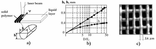
Fig. 1. a) Trace formation of cured polymer on the PCR surface at initiation of the polymerization by the laser beam moving with speed v. b) Dependences of thickness (h) and width (b) of a cured track on the given doze of the irradiation (D/Ec). c) Polymeric lattice obtained at initiation of the polymerization in crossed laser beams. Period of lattice � 7.5 microns, depth � 300 microns.
For the discussed model the parameter Dp, which is accepted when characterizing PCR, is a-1. In Fig. 1b the experimental (points) and model (solid curves) dependences h(D) � d(D) appeared as a result of the polymerization of PCR based on oligocarbonatemethacrylate, known as ���-2, are pictured. It should be noted that Dp and Ec depend on the density of the energy of the initiating impulsions or the radiation intensity under the initiation of the polymerization by using continuous wave laser radiation 5, 12, 13, and the parameters of the polymerized medium, which change in the act of the polymerization. The attempt at modeling of film formation was carried out in 32.
To gain a complete understanding of the process it is necessary to consider the case of the initiation of the polymerization by using a focused beam with Gaussian distribution of the intensity, which moves discretely (by leaps) along the surface of the CPR. In this case the velocity v=0 and it is easy to show, that h(D) and d(D) are determined with the correlations (2) and (3), and the border of the cured area is a rotation paraboloid. However, in this case the dose of the irradiation is
D = Pt/pw02
under the initiation of the polymerization by using continuous wave radiation or
D = FN/pw02
under the initiation by pulses with the density of the energy F.
Thus, by using different ways of irradiation it is possible to get a polymer film (plane), a track (line) or kern (point) on the surface of PCR. These elementary objects can be used for building real copies of the three-dimensional objects by using their computer images. Polymerization photoinitiated by laser radiation possesses high enough resolution and allows to obtain elements of structures with the size of the order of a few mm (Fig. 1b) 20.
 |
3.2. Laser stereolithography
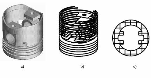
Fig. 2. Sequence of data preparation for a control system of the laser stereolithography machine: a) three-dimensional computer model; b) model slicing into thin (100-200 microns) layers; c) formation of the laser beam trajectory.
The laser stereolithography involves a creation of a three-dimensional model of the object in STL-format (Fig. 2a), its slicing into thin layers (Fig. 2b), calculation of the laser beam trajectory, which reproduces each cross section (Fig. 2c) and the subsequent reproduction of corresponding cross-sections on the surface of liquid photocurable resin by using a focused beam of the laser radiation initiating polymerisation. The absorption coefficient of laser radiation is so high, that it is practically fully absorbed in a thin (0.05-0.3 mm) layer of the photocurable resin. A film of solid polymer is formed in the irradiated area. For the laser beam positioning into a specified point on the PCR surface and for its movement along the calculated trajectory with the given velocity, a computer-controlled two-coordinate scanner is usually used. In the vat containing the liquid PCR the transition from one layer to another is carried out by the movement of the working plate with the part being built on it to the depth equal to the thickness of the next layer. Fig. 3 using the production of the first models of a heart valve as an example illustrates the sequence of layer-by-layer fabrication of a three-dimensional object by using the focused laser beam. Initially the working plate is placed below the surface of PCR at the distance equal to the thickness of the first layer. The first cross-section of the object is reproduced on the surface of PCR. In the irradiated area the solid polymer film is being formed. After the first layer has been formed, the plate with polymer film is dropped to the depth equal to the thickness of the next layer. The second cross-section of the part is reproduced on the surface of liquid PCR by laser beam. The initiation parameters are so chosen that the second layer was reliably �stuck� to the first one. Further the plate is moved at the distance equal to the following layer thickness, and the process is repeated until all the layers will be manufactured. After formation of the last layer the plate is elevated above the PCR surface, the grown part is taken away from the platform, the traces of liquid PCR are removed from the part surface, and the part is dried. The first step to the introduction of the stereolithography into medicine practice is the transformation of the results of the examination of the patients by using X-ray, NMR or ultrasonic computer tomographs into three-dimensional computer model in STL-format.
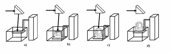
Fig. 3. Sequence of layer-by-layer manufacturing of three-dimensional objects by using the laser stereolithography method: formation: a) of the first layer of the object; b) N layer; c) last layer of the object; d) object, fabricated by layer-by-layer method by using the focused laser beam on vertically moving platform, and taken from the vat with liquid PCR.
3.3. Transformation of tomograms into three-dimensional computer model
The tomograms obtained on a computer tomograph usually represent a set of the grey scale images of cross sections (layers) of an object examined on coordinate z (axial sections). Each element of the tomogram is a function of the density of the object in the appropriate point (x, y, z). In most cases the range from qmin to qmax in the area of the function values q(x, y, z) can be presented by one byte. If this is not the case so the possibility of the shift along the byte grid of brightness gradation is considered. Thus a tomogram can be considered as a three-dimensional image of the density function put in the form of one byte value and described as a three-dimensional matrix of brightness Q(i, j, k).
To translate the tomogram to STL-format we need to construct a mathematical model of the object in a solid body form16,17 . In the general case the mathematical model of a solid body can be presented as:
F(x, y, z) = 0, if there is no object in the given point,
= 1, if there is an object in the given point. (4)
In the case the coordinate x, y, z are determined on a discrete grid:
xi = dx ´ i, i = 0, 1, ..., Nx,
yj = dy ´ j, j = 0, 1, ..., Ny,
zk = dz ´ k, k = 0, 1, ..., Nz,
the function F(xi, yj, zk) represents a three-dimensional two-gradation (0 or 1 bit per pixel) image. Thus, if an image pixel is presented as a cube with the sizes dx´dy´dz,, the translation of tomography data to STL format can be done by transformation of Q(i, j, k) to F(xi, yj, zk). In this case each external cube side is described by two triangles.
For correctness of the transformations we need to determine the order of the real object in the tomogram correctly. In the simple case the relation (1) becomes
F (xi, yj, zk) = 0, if Q(i, j, k) < Q threshold
= 1, if Q(i, j, k) > Q threshold
As our experience of model fabrication has shown, the object of research (for instance, the human skull) is a complex formation possessing a lot of internal cavities and having simply different optical density in the different areas of the object. Geometrical sizes of the skull details can be less than the tomograph resolution. Thus, at lower threshold a signal/noise value, some bones can be merged, and the other ones at higher threshold value can be fallen apart. The correct determination of the object border is possible if all nuances of the mechanism of the tomography scanning of concrete types of objects and the representation of their images are known.
After the determination of the object border the accuracy of the fabricated model is completely determined by the number of image points and the number of layers in the source data. For example, if the distance between the layers is dz= 1.5 mm, and dx=dy = 0.488 mm (512´512 pixels for the field 250´250 mm), then the plastic model will have a step structure with the same accuracy. However, stereolithography permits to receive considerably higher accuracy (�0.1 mm). Consequently, there is a necessity of smoothing the surface of the object model. The attempt to use 3D CAD software for automatic interpolation and formation of the smooth surface failed because of the large amount of processed data (105-107 � points of the surface). In the case of formation of the smooth with different the traditional CAD (for example, Euclid and AutoCAD) are not particularly adequate. So a large volume of interactive work is required.
Besides time problems, in the case of interactive work the probability of an operator�s mistake grows greatly. The problem can be only solved by creation of the special program software. Program software 16 (program 3Dview) devised at ILIT RAS executes the following functions:
- reads the source data of computer tomographs in DICOM, BMP, PCX formats;
- makes normalization of brightness and records the image in a form of a three-dimensional matrix of brightness (byte per pixel);
- determines the border of the object in tomograms and forms a three-dimensional solid model of the object;
- makes filtration of a solid model (removes small-sized lonely fragments and cavities);
- if necessary, the operator-expert can execute hand-operated editing of obtained solid model for removing artifacts and internal closed cavities, which do not contain useful information;
- translates the solid image to the STL format which is conventional for laser stereolithography machines.
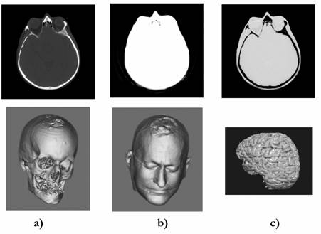
Fig. 4. Tomogram received by using an X-ray computer tomograph (above) and examples of the transformation of the tomogram for construction of: a) a skull of a patient; b) his head; c) his brain. The typical result of tomography research: 50-400 tomograms.
3Dview software permits to work with tomograms presented in DICOM format (the standard devoted for exchange of medicine information) and in any standard graphic format (BMP, PCH, etc.).
Tomograms
contain a great body of information. Its stratification allows by using
the
results of one examination of the patient to build a computer model in
STL
format, for example, a skull of the patient, its outward, and to
differentiate,
for example, the patient�s brain (Fig. 4). However, it should be noted
that
construction of computer models of brain and other organs demands the
advance
editing of tomograms, that requires the detailed knowledge of anatomy,
and hand
tomogram processing by using software for image processing, is time
consuming.
If you use 3Dview program it is enough for computer models construction
of bone
fragments of the human skeleton from the data obtained by using X-ray
computer
tomograph to set the correct brightness level corresponding to the
border of
bone tissue.
4. Operative fabrication of plastic BIOMODELS
For the first time in Russia the plastic copy of a fragment of an alive human skull (a lower jaw of the ten-year-old girl with the diagnosis of the vascular tumour (haematoma) on the right) was fabricated from the results of the computer tomography on 27 February 1999 20,21.
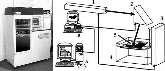
Fig. 5. Photo (on the left) and scheme (on the right) of the laser stereolithography machine based on a continuous HeCd laser. A. Computer modeling and preparation of the data for the machine control system. B. Control computer. 1 � HeCd laser; 2 � two-coordinate (X-Y) scanner; 3 � elevator (Z-coordinate); 4 � vat with liquid PCR; 5 � platform. The machine is also equipped with the systems for stabilization of PCR level (accuracy +/�10 microns), smoothness of PCR surface, calibration of a scanner field and stabilization of a working chamber temperature.
A suitable set of tomograms for construction of a three-dimensional computer model was obtained by using the X-ray tomograph SOMATOM CR (Siemens Co.) at St. Vladimir Children's Clinic (Moscow). The fabrication of the plastic model was carried out on the laser stereolithography machine LS-250/E. Its photograph and scheme are presented in Fig. 5.
Nowadays the scheme of the operative fabrication of plastic biomodels (Fig. 6) functions and involves
- scanning of a patient by using a computer tomograph in a special clinic;
- obtaining of axial slices in DICOM format;
- tentative processing of the tomograms for the purposes of determination of the field of interest;
- packing of the tomograms and their transmission along electronic webs to ILIT RAS;
- construction of a three-dimensional computer model by using obtained tomograms and its transformation in STL format;
- fabrication of the plastic biomodel on the laser stereolithography machines LS-120 or LS-250 which were constructed and made at ILIT RAS.
This scheme has functioned since 1999 and more than 10 Russian clinics have used it. By now plastic biomodels have been made for 178 patients.
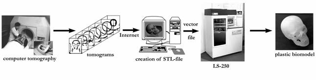
Fig. 6. Scheme of rapid manufacturing of plastic biomodels by using the results of patients examinations on computer tomographs in special clinics.
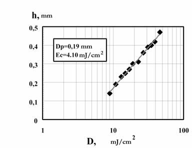 |
The plastic biomodels are usually fabricated as layers with 0.3 mm thick from photocurable composition, called IPLIT-1. In Fig. 7 photosensitivity of the composition IPLIT-1, that determines the productivity of LS-250 machine, is described as the dependence of the thickness of a cured layer (h) on a dose of irradiation (D). Main characteristics of the solid polymer before and after boiling for an hour are given in table 1. Plastic models made of IPLIT-1 withstand sterilization of 120�� in the formalin steam without any form losses as well as ozone and ethylene oxide sterilization followed by a long time degassing (100-200 hours) in vacuum.
Fig. 7. Dependences of the thickness of the cured layer (h) on an irradiation doze (D) by using HeCd radiation (λ=325 nm) for polymerization of PCR IPLIT-1. They are obtained with the radiation power P=15 mW and the laser beam with the diameter on the PCR surface equal to 0.25 mm. The doze of an irradiation was changed by variation of the moving speed of the beam on the PCR surface.
Plastic biomodels are used for preparation and planning of operations in maxillofacial surgery, surgery of the neck and spine, thoracic surgery, orthopedics and neuro-surgery and also for operative fabrication of implants made of different materials (most often of plastics based on polymethylmethacrylate and titanium, less common of autogenous bone tissue) and their preoperative adjustment. More often (approximately 80% of all cases) biomodels are used for elimination of posttraumatic (consequence of traumas and operations for elimination of pathologies) and congenital (usually with children) defects in maxillofacial surgery. In this field of the surgery the cosmetic effect as a consequence of the operation also plays an important role.
The effect of the tentative planning of operations by using plastic biomodels makes itself evident in the considerable decrease of the operation duration (up to three times) 21, that is especially important for small patients as the duration of stay under general anaesthetic for them is strictly limited, in the improvement of the qualitative characteristics that leads to the decrease of the rehabilitation period and to the fall of the cost of the operations.
Table 1. Typical properties of the samples made of PCR IPLIT-1.
|
Measurement |
Part |
Part after 1 hour boiling in water |
|
Green part |
||
|
Impact resistance, kJ/m2 |
1.2 |
0.65 |
|
Flexural strength, N/mm2 |
71 |
22 |
|
Flexural angle |
16.7� |
8.5� |
|
Hardness HB, �Pa |
108 |
103 |
|
Post-cured resin |
||
|
Impact resistance, kJ/m2 |
2.6 |
2,2 |
|
Flexural strength, N/mm2 |
89 |
29 |
|
Flexural angle |
17.6� |
7.0� |
|
Hardness HB, �Pa |
140 |
110 |
5. OPERATIVE Fabrication of implants
Three schemes of the implant fabrication from biocompatible materials on a base of methylmethacrylate ((Polacos-R, Palamed-G co. Merc Biomaterial GmbH, Germany) have been worked out and sampled together with the N.N. Burdenko Institute of Neuro-surgery 23:
1) hand moulding (�modeling�) of the implant needed for elimination of the defect on the plastic model of the skull fragment of the patient;
2) construction of a plastic master of the implant, and with the help of the master fabrication of a form for casting from heat-resistant rubber;
3) construction of the computer model of the press-form and fabrication of its elements by the laser stereolithography method.
The first scheme does not demand the computer model construction of the implant; its quality depends only on the professional surgery skills. The method of forming of implants by using press-form elements which were made by the laser stereolithography method, was found operative and effective, as one does not necessarily need high pressure and temperature exceeding 100�� when forming implants out of Polacos-R and Palamed-G (Fig. 8). The practice (more than 40 operations by the end of 2002) showed, that fabricated by this method implants do not demand extra adjustment in the operating room. It should be noted, that plastic and rubber forms can be used for production of transitional wax models that can be changed into implants and prosthetic appliances from titanium and other alloys by using methods of traditional casting.
For realization of the second and third scheme it is necessary to construct the computer implant model. Nowadays we are developing three methods of the construction of the computer implant models. The essence of the first method is �editing� of the tomograms. The base of the second method is the use of the object symmetry. The essence of the third method is the use of a suitable virtual �donor� � a computer skull model from the database involving more than 100 skulls of different patients.
In the first case an operator fills in the missing details of the object, for example, a skull or jaws. For this purpose Paint, Photoshop or any other graphic software can be used. The obtained set of the edited tomograms is transformed into a three-dimensional computer model and then into STL file by using 3Dview. A three-dimensional computer model of the implant is obtained by the subtraction of the object constructed by the initial tomograms from the object constructed by the edited tomograms. This method allows solving practically any problems connected with the construction of the computer model of the implant. However, it is labour-intensive and demands detailed knowledge of the object and special professional training.
When the injury is on the left or on the right a simple apparatus of Boolean operations (integration, subtraction and intersection) allows to solve the problem of the construction of the implant model more efficiently; that is often the deciding factor of using this apparatus. In this case the object is divided into two parts by the symmetry plane. One of the parts is transformed into its mirror copy. Two objects are superposed and the injured fragment is subtracted from the mirror copy of the uninjured fragment. Since the absolute identity of right to left does not exist, the implant, the result of the subtraction, demands to be completed by the computer modeling or the machine processing of the plastic model fabricated by the method of laser stereolithography.
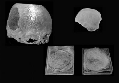 |
Fig. 8. Plastic models of a fragment of a skull, an implant for elimination of defects, and elements of a mould for manufacturing a biocompatible implant from Polacos-R and Palamed-G.
If the symmetry cannot be used, the method of using the virtual donor is effective. The model of the skull, suitable for the patient, is chosen from the data base, the appropriate fragment is subtracted. Then it is scaled, transformed and superposed by base point with the model of the patient skull through the translations and rotations. Further, as in the previous case, the model of the implant is formed by the use of Boolean operations. The development of this method allowed practically to abandon the construction of the computer models by the labour-intensive method of editing tomograms, even in forming implants for the central zone of the face that is more complicated when modeling.
The achieved accuracy and speed of the construction of the plastic biomodels and implant models made by the method of laser stereolithography made the task of the direct fabrication of biocompatible implants for the elimination of defects of bone tissue more attractive since the method solves any problems connected with the construction and making of a practically disposable rig (press-form, moulding form).
6. LASER STEREOLITHOGRAPHY AND ULTRA-CRITICAL CLEANING FOR
THE FABRICATION OF BIOCOMPATIBLE AND BIOACTIVE IMPLANTS
The base of PCR for laser stereolithography is the extensive class of acrylic monomers and oligomers, which effectively polymerize by a radical mechanism. At the same time, for the past 50 years acrylic plastics (with different fillers and without them) are widely used in medicine as bone cement and the material for the implant fabrication. For example, photohardening polymer compositions are quite often used in dentistry as a sealing material. However, using acrylic plastics in clinics is often accompanied by different complications, right up to neuroses and rejection of implants 24. Primarily it is connected with different toxic admixtures (monomers, low molecular weight oligomers, initiators, solvents and suture agents) contained in these plastics, which could penetrate in surrounding fabrics. The important circumstance is also the fact that bone fragments are the objects with complicated morphology. So the actual task is the task of fabrication of implants with structure similar to bone fabrics, and which do not contain toxic admixtures and which stimulate the growth of the fabric and ensure the integration with a regenerated bone. The development of chemistry and the improvement of the technology of syntheses of plastic stimulated the creation of practically non-toxic materials with sharply reduced concentrations of soluble components. Among these materials are, for instance, polyfunctional (meth) acrylic oligomers, which are characterised by high reactionary ability and polymerization of which runs with forming a three-dimensional spatial net 25, 26 (unlike traditional linear polymethylmethacrylate chains). At the degree of conversion equal to approximately 50%, a polymer that is practically insoluble in organic solvents is formed. The structure of the oligomer block between the ending reactive groups and the parameters of the spatial net define mechanical and physics-chemical characteristics of the finishing product. This allows to make implants with given biochemical and biomechanical characteristics or use them for construction of a bioinert polymer matrix for forming bioactive implants.
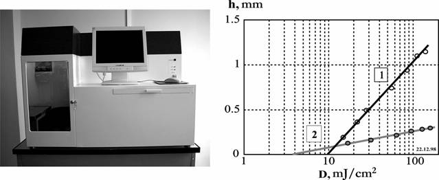
Fig. 9. Photo of LS-120 machine (on the left) and dependences of the thickness of the cured layer (h) from an irradiation doze (D) (on the right) during the polymerization of the pure (1) and GAP-containing OKM-2 (2) They are obtained with the radiation power P=10 mW and the laser beam diameter on the PCR surface 0.12 mm. The doze of irradiation is changed by variation of the moving speed of the beam on the PCR surface.
Oligocarbonatedimethacrylate (OKM-2), synthesized at the Institute of Chemical Physics RAS was used as a material for construction of a polymer matrix and fabrication of control pure polymer patterns. The photo-initiated polymerisation of this oligomer by laser radiation is investigated in sufficient detail 12, 27, from the view point of the possibility of its use in laser stereolithography.
Phosphates
of calcium enter the
composition of bone
fabric. So monodispersion powder of hydroxyapatite (Ca10(PO4)6(OH)2
) with granules measuring about 1 mm,
synthesised and supplied by �Polistom� firm (Moscow), was used as a
bioactive
addition. The mineral-polymer composition was prepared by the addition
of the
powder of hydroxyapatite (HAP) into OKM-2 and careful stirring of the
composition. 2.2-dimethoxy-2-phenylacetophenone was used as a
photoinitiator of
the radical polymerisation. At first because of the abrupt viscosity
increase
the concentration of HAP does not exceed 30% by weight. On Fig. 9 the
dependences of the cured layer depth (h) on the irradiation dose (D)
for pure
OKM-2 (1) and OKM-2 containing HAP obtained on LS-120 (Fig. 9) are
presented.
The scheme of
LS-120 is identical to the scheme presented in Fig. 5. For production of h=0.2 mm the
irradiation dose D=30 mJ/cm2
is necessary. The simple
estimate has shown that the implant fabrication of 100 cm3
volume
and by h=0.2 mm layers (approximately 250 layers, an average square of
a cross
section 20 cm2) with the power of radiation 15 mW and the
time
expenditure for travel of the work plate (Fig. 3) 15 s for a layer,
takes about
4 hours.
For
the first series
of the examination of the osteal tissue response towards the implants
fabricated by the laser stereolithography method, carried out at white
rats
(the lines �Vistar�), implants of two types were made: cylinders of 3
mm in
length with a diameter of 1.5 mm and plates with sizes 30x10x1.5 mm.
The
satisfactory results of this series (mineral-polymer implants
fabricated by the
laser stereolithography method stimulate bone formation and integrate
with
osteal tissue 28) stimulated the work for improvement of
the
technology of the fabrication of bioactive implants with the purpose of
production of samples with the structure similar to the structure of
osteal
tissue.
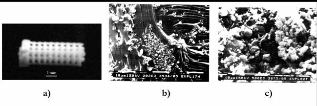
Fig. 10. Photo of the sample made of a mineral-polymeric composition, for implantation to white rats (a) and its structure before (b) and after (c) processing in supercritical CO2.
The experiments on fabrication of bioactive implants were carried out on the laser stereolithography machine LS-120 (the photo in Fig. 9). It allowed the structures with resolution 50-200 mm to be formed, depending on the used material. However, the typical size of cellular structures of osteal tissue is approximately one order lower. In the works 29, 30 it was shown by the example of polyacrylates and polystearol, that processing of these polymers in ultra-critical CO2 allows to obtain structures with controlled size of pores and their concentration. Processing of these polymers in ultra-critical CO2 also allows to significantly decrease the concentration of toxic admixtures 31, that largely improves their compatibility. So, for the second series of the medicine-biological experiments, structural (Fig. 10) and monolithic patterns fabricated by laser stereolithography method underwent processing in ultra-critical CO2. For this purpose the patterns were placed into an autoclave made of stainless steel (max. pressure and temperature were 300 atmospheres and 200� accordingly). The parameters of the medium in the autoclave (pressure, temperature and CO2 expenditure) were regulated and controlled by the PC based automatic system of control. As a result, HAP contained patterns with the characteristic size of pores in the range 5-30 mm were obtained.
The structural
patterns fabricated by laser stereolithography method, which had
undergone
processing in ultra-critical
CO2, were
implanted to white rats of
the lines �Vistar�. Just as in the first series of the experiments
mineral-polymer
implants stimulate bone formation and
integrate with osteal tissue.
However, for structural implants, which had undergone processing in
ultra-critical CO2, the area of
direct
integration with
regenerated osteal
tissue is by at
least an order higher.
7. conclusion
Computer biomodeling, laser stereolithography and the procedure of rapid manufacturing of bone fragments, plastic copies and implants, created on their basis are successfully promoted to medical practice. By the end of 2002 plastic biomodels of bone fragments of a skeleton were made on LS-250 for preparation and planning of operations on 178 patients in 10 clinics of Russia. The pilot version of the program 3DView was developed for transformation of tomography examination results. In more than 80 % of the cases plastic biomodels were used for preparation of maxillofacial operations in which the cosmetic effect from operative intervention was very important. Computer modeling of implants, manufacturing of those implants and moulds to form the implants from biocompatible materials were made for 40 patients by using LS-250. In 45 cases computer modeling and manufacturing of biomodels were carried out for children at the age of 3 to 14 years. For these patients the operation duration is a very important factor. The results of the experiments have shown, that operation planning and preoperative adjustment of implants and endo-prosthetic appliances by using plastic biomodels decrease the operation duration up to 3 times (from 6-10 to 3-4 hours).
The mineral-polymeric composition has been developed. It was used in the fabrication of implants for white rats. The experiment results have shown that the implants made by the method of laser stereolithography stimulate bone formation and integrate with osteal tissue. Processing of implants made by laser stereolithography in supercritical CO2 decreases their toxicity and approaches their structure to the structure of the osteal tissue which improves the osteal-inductive and osteal-integrative properties of the implants.
References
- Rapid Prototyping & Manufacturing: Fundamentals of Stereolithography, P.F. Jacobs, Editor, Dearborn MI, Society of Manufacturing Engineers, 434 p., 1992.
- Stereolithography and Other RP&M Technologies, P.F. Jacobs, Editor, Dearborn MI, Society of Manufacturing Engineers, 451 p., 1995.
- A.V. Evseev, V.Ya. Panchenko, V.P. Yakunin, in Russia National Conference �Laser Technologies �93� (ILLA �93), p. 9, Shatura, 1993.
- A.V. Evseev, S.V. Kamayev, M.A. Markov, A.N. Nikitin, M.M. Novikov, V.Ya. Panchenko, V.P. Yakunin, �Rapid objects manufacturing from liquid photo-sensitive compounds induced by pulsed and CW laser beam�, in 5th International Conference on Industrial Lasers and Laser Applications �95, Vladislav Ya. Panchenko, Vladimir S. Golubev, Editors, Proc. SPIE Vol. 2713, 370, 1996.
- A.V. Evseev, S.V. Kamaev, E.V. Kotsyuba, M.A. Markov, M.M. Novikov, V.Ya. Panchenko, N.M. Semyoshin, V.P. Yakunin, Avtomatizatsiya Proyektirovaniya 2(12), 8, 1999 (in Russian).
- V.Ya. Panchenko, Information Technologies and Computing Systems 1, 13, 2001 (in Russian).
- B.H. Cumpston, S.P. Ananthavel, S. Barlow et al., Nature 398, 51, 1999.
- S. Juodkazis, M. Horyama, M. Miwa, M. Watanabe, A. Marcinkevičius, V. Mizeikis, S.Matsuo, H. Misawa, �Stereolithography and 3D micro-structuring of transparent materials by femtosecond laser irradiation�, in Laser and Laser-Information Technologies, Vladislav Ya. Panchenko, Vladimir S. Golubev, Editors, Proceedings of SPIE Vol. 4644, 27-38, 2002.
- C.G. Roffey, Photopolymerization of Surface Coatings, New York, 1982.
- A.F. Maslyuk, V.A. Khranovskiy, Photochemistry of Polymerizable Oligomers, Nauk. Dumka, Kiev, 192 p., 1989.
- C. Carre, C. Decker, I.P. Fouassier, D.I. Lougnot, Laser Chem. 10, 349, 1990.
- A.V. Evseev, M.A. Markov, Kvantovaya Elektronika 21, 491, 1994 (in Russian).
- A.V. Evseev, M.A. Markov, V.Ya. Panchenko, V.P. Yakunin, Proc. of 8th European Stereolithography User Group Meeting, 7-8 October 1996, Darmstadt, Germany.
- J. Bill, J.F. Reuther, J. Muehling, Deutsch Zahnarztl Z 48, 789, 1993.
- R. Lewis, Biophotonics 2(2), 34, 1995.
- E.V. Kotsuba, A.V. Evseev, S.V. Kamayev, M.A. Markov, M.M. Novikov, V.Ya. Panchenko, N.M. Semeshin, V.P. Yakunin, Proc. of 8th European Stereolithography User Group Meeting, 7-8 October 1996, Darmstadt, Germany.
- S.S. Abramov, N.I. Boldyrev, A.V. Evseev, E.V. Kotsyuba, M.M. Novikov, V.Ya. Panchenko, N.M. Semyoshin, Opticheskaya Tekhnika 1 (3), 45, 1998 (in Russian).
- S.S. Abramov, N.I. Boldyrev, A.V. Evseev, E.V. Kotsyuba, M.M. Novikov, V.Ya. Panchenko, N.M. Semyoshin, V.P. Yakunin, Medicolegal Examination 41 (3), 13, 1998.
- J.T. Lambrecht, F. Brix, H. Gremmel, in Forensic Analysis of the Skull: Craniofacial Analysis, Reconstruction and Identification, M.Y. Iscan, R.P. Helmer, Editors, New York, �. 97, 1993.
- A.V. Evseev, V.Ya. Panchenko, Proceedings of SPIE Vol. 4070, p. 401, 1999.
- V.V. Roginskiy, A.V. Evseev, E.V. Kotsyuba, V.K. Popov, A.V. Pasechnikov, A.L. Ivanov, O.Z. Topolnitskiy, Detskaya Stomatologiya 1-2/(3-4), 92, 2000.
- http://www.laser.ru/rapid
- A. Kravtchouk, A. Potapov, V. Kornienko, S. Eropkin, V. Panchenko, A. Evseev, V. Stuchilov, in Neurotrauma, A. Potapov, L. Likhterman, K.R.H. von Wild, Editors, The N.N.Burdenko Neurosurgery Institute, pp. 187-190, 2002.
- A.I. Volozhin, T.I. Sashkina et al., Allergy and Other Forms of Intolerance in Stomatology, Moscow, 92 p., 1996 (in Russian).
- A.A. Berlin, T.Ya. Kefeli, G.V. Korolyov, Polyetheracrylates, Nauka, Moscow, 1967 (in Russian).
- V.K Grishenko, A.F. Maslyuk, S.S. Gudzera, Liquid Photopolymerizable Compositions, Nauk. Dumka, Kiev, 1985.
- A.V. Evseev, M.A. Markov, Kvantovaya Elektronika 21, 495, 1994 (in Russian).
- E.N. Antonov, A.V. Evseev, M.A. Markov, V.Ya. Panchenko, V.K. Popov, O.Z. Topolnitskiy, A.I. Volozhin, A.A. Doktorov, S.G. Kurdyumov, Opticheskaya Tekhnika 1 (13), 55, 1998 (in Russian).
- S.K. Goel, E.J. Beckman, Polymer Engineering and Science 34, 1137, 1994.
- E. Kung, A.J. Lesser, T.J. McCarthy, Macromolecules 31, 4160, 1994.
- A.I. Volozhin, O.Z. Topolnitskiy, V.K. Popov et al., News in Stomatology N 3, 32, 1999 (in Russian).
- A.V. Evseev, A.N. Nikitin, Izvestiya RAN. Ser. Fizicheskaya 57(12), 132, 1993 (in Russian).