A detailed treatment of a laser system that holds great promise for high-power applications includes design procedures and parameter tradeoff considerations
David R. Whitehouse
Manager, Laser Advanced Development Center
Raytheon Co., Waltham, Mass.
The
great interest in carbon dioxide lasers stems from their continuous power
capability, high efficiency and ease of construction. Table
1 graphically illustrates their advantages
over other gas lasers.
| Laser Type | Linear Power Density
W/m |
Maximum
Power
W |
Power
Efficiency
percent |
| He-Ne | 0.1 | 1 | 0.1 |
| Argon | 1-10 | 50 | 0.1 |
| CO2 | 60-80 | 1200 | 15-20 |
|
The Gas-Flow Discharge Principle 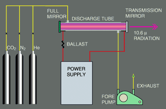 |
The CO2 laser system is shown in Fig. 1. Three gases (CO2, N2 and He) are mixed and fed into one end of a discharge tube at a pressure of a few torr. The gas flows down the end of the tube in about one second and is pumped out the far end with a mechanical forepump. An electrical discharge is maintained between the metallic end flanges of the tube. The ballast resistance is required because of the negative dynamic resistance of the discharge. With a fully reflecting mirror on the left and a partially transmitting mirror on the right, the device becomes a laser which radiates in the far infrared at 10.6 microns. |
The CO2 laser is comparable in simplicity, if not in size, to the microwave klystron. Both have a high-Q electromagnetic cavity, a highly efficient power-output coupling technique, and an active medium fed from a simple dc power supply. Also, with slight modifications either can be used as an oscillator or an amplifier.
The possibility of using molecular vibrations for laser action was clearly pointed out by Polanyi in 1961. More recently, Patel has described in some detail the laser action on the vibrational-rotational (V-R) transitions of CO2 in an electrical discharge. Shortly afterwards, progress towards high power and efficiency was achieved by Patel with the addition of N2 and by Moeller and Rigden with the addition of He. Other molecular systems have been made to lase, but so far CO2 is the most important power producer.
Many
parameters affect the design and operation of the CO2 laser. The gas discharge
can be powered with dc, ac, RF, repetitive pulses, or any combination thereof.
The mirrors can be fixed, rotated for Q-switching, or vibrated for reactive
Q-switching. The discussion here will be limited to dc excitation with
fixed mirrors. Most of the technical data were obtained from Horrigan
and Whitehouse;
more detail can be obtained by referring to their reports.
OPTIMIZING
THE CO2 LASER
Performance of CO2 lasers may be optimized in several ways: Maximize multimode power; maximize single-mode power; maximize efficiency; and/or minimize size and complexity. The parameters that affect such optimization for flowing gas systems are:
- Tube length, diameter and wall temperature
In addition,
for sealed-off CO2 lasers, it appears that the gas purity and tube materials
are also important. Optimization is by no means simple, because the various
parameters are strongly interrelated. All results, therefore, should be
viewed only as indicative of performance trends. The engineer should be
prepared to perform experimental exploration of his own system.
LASER
OPTICS
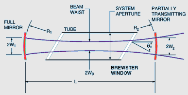 |
The most common electromagnetic laser cavity consists of two mirrors with circular apertures, as shown in Fig. 2. The reflecting surfaces are segments of spheres with radii R1 and R2 and separated by a distance, L. The best alignment occurs when the line joining the centers of curvature is coincident with the geometrical axis through the mirror centers and the laser medium. |
For gas lasers, these mirrors may be directly mounted on the discharge tube, or one or both of them may be externally mounted. If externally mounted, the vacuum exists between optically polished flat transmitting windows mounted at the Brewster angle given by Equation A where n is the refractive index of the window material. The advantages of a Brewster-window system are that the laser radiation is polarized and that mirror tuning is independent of the tube. Its disadvantage is that the windows must withstand the high-power laser radiation field inside the optical cavity.
![]()
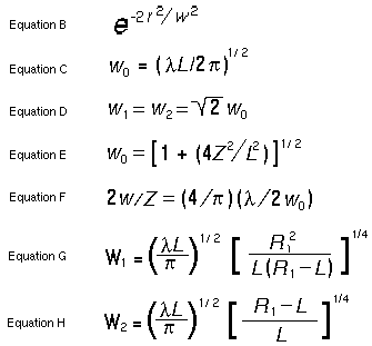
If system aperture is sufficiently large, the radiation pattern inside the laser cavity can be approximated by a summation of normal modes--each with a different frequency and spatial distribution determined by the mirror curvatures and spacing. The longitudinal modes have a radial gaussian power distribution approximated by Equation B where the gaussian width, w, or spot size varies as a function of axial position. One such mode is sketched in Fig. 2. For convenience the confocal geometry is shown with R1 = R2 = L, where the spot size at the beam waist is given by Equation C and at the mirrors by Equation D.
The spot size generally increases as a function of distance from the beam waist; the relation is described by Equation E. This leads to the normal full-angle beam divergence in the far field given by Equation F.
At 10.6 microns, and with a cavity length of 1 meter, the waist diameter is 2w0 = 2.6 mm . If large-diameter tubes and mirrors are used, the radial or off-axis modes may be generated, thus contributing to the total output power. However, for single-frequency operation the size of the longitudinal mode must be increased by increasing the curvature of the mirrors. It is usually desirable to make the transmitting mirror optically flat. Thus, with R2 = infinity , the spot sizes at the two mirrors are given by Equations G and H.
If R1 is now increased to 50 meters, the spot diameter increases to about 10 mm and a single mode begins to fill a reasonable volume. Ideally, the curvature could be further increased, depending on available optical components.
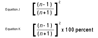
Output from the cavity can be obtained in various ways. The best of these is to use an output transmitting mirror with a uniform transmission coefficient over the whole aperture. Other techniques include hole coupling, spot coupling and iris coupling; but these tend to generate irregular modes in the cavity and should be avoided. When coupling through a transmitting mirror, it is possible to see the Fresnel reflection (whose magnitude is given by Equation J) from the bare mirror material as the feedback for the oscillator. Otherwise, the mirror may have a multilayer dielectric coating on one face to achieve any desired reflectivity while the other face has an antireflection coating. Coatings for high-power CO2 lasers operating at 10.6 microns are not very reliable, so bare surface reflectors should be used if possible for such applications. Another technique is to use a plane parallel mirror which then acts as a Fabry-Perot etalon and has any degree of reflectivity from 0 to a value given by Equation K, depending on wavelength. The reflectivities and physical properties of presently available materials for use at 10.6 microns are given in Table 2.
OUTPUT SPECTRUM
The output spectrum
of the CO2 laser is determined by the exact mirror separation and its relationship
to the CO2 amplifying medium.
|
Gain Characteristics in CO2 Laser 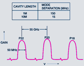 |
When the discharge is on and the tube is not lasing, the medium exhibits a single-pass gain given by Equation L, where alpha is a function of frequency (see Fig. 3, and refer to "CO2 Laser Theory"). This gain curve is a series of bumps or lines about 50 MHz wide where each line corresponds to one of the J rotational levels of the 001 vibrational state with an excess density over the J + 1 level in the 100 state. |
The wavelengths of these lines are determined by the CO2 molecule and are separated on the average by about 55 GHz.
![]()
The widths of the
lines are determined mainly by the thermal spread and, to a lesser extent,
by the collision broadening. The total area under all the P
transition gain curves is proportional to the difference in density between
the 001 and the 100 vibrational levels. The distribution among the P
branch lines is determined by the effective rotational temperature of the
molecules. At room temperature the peak gain or area occurs when P
= 20. The longitudinal cavity modes occur at regular frequency intervals
equal to c/2L, where c is the
speed of light in the medium. For a 1 meter cavity, these modes are separated
by 150 MHz, which is larger than the 50 MHz Doppler width of the various
P transitions. If it is assumed that the radial modes have
been suppressed by appropriate choice of mirror curvature and the tube
diameter, the longitudinal mode that experiences the highest gain under
any of the P transitions will be the first mode to grow in
time. For example, if one mode happens to be at the center of P20,
it will dominate the oscillation. The other modes that happen to be within
P18 or P22 may not oscillate, since the collisional
relaxation between the rotational levels, and hence P transitions,
is very fast.
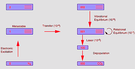 |
In Illustration C, this time is 100 nanoseconds - sufficiently small, when the power density in the cavity becomes high and burns out the inversion on P20 for the other rotational levels to feed into this one and all of the gain profiles to decrease together. |
The P branch transitions are thus homogeneously broadened; only one mode tends to oscillate, and this one supplies most of the available power from the vibrational level. As the length of the cavity slowly changes, the mode at the center of P20 will shift off center with a resultant decrease in the output power. If another mode peaks up at the center of P18 or P22, it will take over and supply the available power. It is also possible for several P branches to oscillate at once if all the modes are off in the wings of the profile. The other extreme occurs for a long cavity, such as a 10 meter cavity where the mode separation is 15 MHz. Here, the P branch with the maximum gain always oscillates, because one mode is always within the peak of the Doppler gain profile.
DISCHARGE PROPERTIES
Although the CO2, N2, and He discharge can be operated either with dc, ac, RF, or pulses, it appears that the maximum average output power can be achieved either with dc or low-frequency ac applied directly to the electrodes. The power is less with RF, probably because it is hard to keep a long length of the discharge uniformly excited. Where the discharge must be pulsed, the average power may be only 1/10 to 1/8 of the dc value; also the optimum pressure and output coupling conditions change.
Electrical characteristics
of the CO2 laser are high voltage and low current with a negative dynamic
resistance. Except for the large negative resistance, the discharges are
similar to cold-cathode, glow discharges. In flowing gas systems such as
these, almost any material may be used for the electrodes. For glass tubes
which are bolted together with O rings, metal flanges between the sections
are most convenient. For glass-to-metal seal systems, the Kovar seals themselves
can be used for the electrodes.
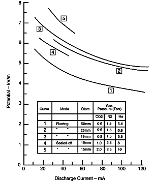
| The volt-ampere curves for typical tubes and gas mixtures are given in Fig. 4. To obtain these curves, the voltage was converted to field strength by dividing the tube voltage by the electrode separation. Therefore, except for the small error introduced by the cathode drop, these data can be scaled to any length tube. The negative resistance represented by these curves varies from about 50 kW/m at low currents to 10 kW/m at high currents, and the circuit requires a ballast resistance for current stabilization. | Fig
4. Volt-ampere Curves for CO2 Lasers
 |
CO2 LASER CHARACTERISTICS
Important CO2 laser characteristics are high unsaturated gain, high-power output and good efficiency. It has been experimentally determined that gain is a strong function of tube diameter and that output power is essentially independent of diameter. The measured gain for three tube diameters is plotted in Fig. 5 as a function of the tube current at optimum gas pressures for maximum output power. The gain curves for larger diameter tubes can be substantially changed simply by adding some turbulence to the gas flow. The gain reaches its maximum at low currents, falling off as current increases. This fall-off is apparently caused in part by the heating of the gas on the tube axis. Note that the current for maximum gain is smaller than that for maximum output power.
These tubes can be used as amplifiers as well as oscillators by simply directing a laser beam down the length of the tube. Once the power density in the beam exceeds 25 to 50 W per square cm, the gain becomes saturated and decreases to a low value. Thus, for power densities much less than this figure, power amplification is achieved by using small bore tubes at low currents. For power densities much larger than 25 to 50 W per square cm, the power amplification if almost independent of the tube bore; thus, the tube should be operated at currents which produce maximum power.
When used as an oscillator, the laser output and efficiency will vary with the discharge current, as shown in Fig. 6. For this laser, a peak output power of 230 W at 17 per cent efficiency was achieved with 120 mA discharge current. The peak efficiency of 21.5 per cent occurred at 60 mA. Optics used produced a multimode pattern. If only longitudinal modes were desired, the maximum power would decrease about 20 per cent. Because of high-efficiency power conversion, the laser action has a strong effect on the volt-ampere characteristics. Under lasing conditions, the whole potential-discharge current (No. 1 in Fig. 4) is raised about 200 V/m or a total of about 600 V.
Research data lead to the conclusion that the available power from different-sized tubes is independent of diameter and linearly proportional to length. If optimally designed, a CO2 laser should thus produce from 60 to 80 W per meter-length of discharge in the optical cavity. This has proven true in tube lengths from 1 to 20 m.
So far, the optimum transmission coefficient of the output mirror has been determined by trial and error. Ideally, to achieve the maximum power, the transmission coefficient for a tube with a given diameter and length should be known. Fortunately, the power curve is quite broad with variation in transmission coefficient, so exact values are not needed. Based on tube diameter and discharge length, a rough estimate of the required transmission coefficients can be obtained from Fig. 7.
The discharge tubes should normally have water jackets for cooling, but in the flowing gas system the effect of cooling is only marginal. For example, the output power from the 50 mm bore tube may decrease by only 10 per cent as the wall temperature increases 30° to 40° C. Sealed-off lasers, however, do not dissipate their power by dumping the stored energy into the flowing gas, but must dissipate their heat to the walls. Thus, water jackets are a must in order to cool the central gas and thereby avoid loss in output power.
Two other important parameters are the partial pressures and the flow speed of the gas. The picture is complex, however, because all the variables are interrelated. For example, if the nitrogen pressure is changed, the output power may decrease; but it could conceivably be recovered by a change in the transmission coupling or discharge current. Nevertheless, when all the parameters are optimized and only one of the partial pressures is changed incrementally around its optimum value, the output power will change in accordance with Equation M where P = output power and p = partial pressure. For nitrogen and helium, alpha is about 0.5; for CO2, about 2.0
Power increases with
pumping speed at about 0.2 W/m/cubic ft/min to at least 100 cubic ft/min.
Below about 10 cubic ft/min, the power decreases rapidly, and this region
of operation is to be avoided for high-performance operation.![]()
DESIGN PROCEDURES
Problem: What are the parameters for a CO2 laser with a certain power level, P0, and a minimum physical length?
Assuming an effective pumping speed of at least 15 cubic ft/min and that the partial pressures and discharge current can be adjusted during operation, the following procedure can be followed:
1. For a multimode output power of P0 watts, the active length of the discharge medium is the first parameter to be specified.With careful optical design, this length could also produce P0 watts with only longitudinal modes; however, a 20 to 30 per cent increase in length will safely handle this additional requirement.Length = P0/60 meters2. Next, choose the optical material for the output mirror and determine the tube diameter. If uncoated optics are desired, consult the list of usable material to determine what reflectivities are available. With the reflectivity and tube length specified, determine the tube diameter from Fig. 7. If the tube diameter is specified from other considerations (e.g., available power supply voltage), then Fig. 7. is used to determine the required reflectivity. If necessary, this reflectivity can be obtained with dielectric coatings on an appropriate substrate. Beyond this consideration is a power limitation caused by heating of the optics. The power limitations of materials which have been used are given in Table 3.
3. Design the optics, using the mode-size calculations to fill the volume of the tube. The full mirror is usually a gold-coated substrate of glass or metal. Gold only absorbs about 1.5 per cent of the incident energy and is chemically inert. The choice of an internal-mirror tube or a Brewster window tube with external mirrors is usually determined by the application. With high-power lasers, the Brewster windows must transmit a high-intensity beam, they should therefore be avoided, if possible.
4. Design the power supply with tube length and diameter in mind, using Fig. 4 The applicable curve in Fig. 4 is determined by tube diameter, and the over-all tube voltage is determined from the ordinate multiplied by the tube length. The power supply voltage is then determined by adding sufficient voltage for the required ballast resistor and the increase in tube voltage caused by lasing. The optimum current level is somewhat dependent on diameter, and several values are indicated in Fig. 5. For long tubes, the required voltage becomes excessively high and the total discharge path must be divided into parallel sections. For dc excitation, this requires careful balancing of the electrical circuit and the gas-flow conditions.
5. Consider physical length of the laser. If it must be held to a minimum, it is possible to fold the laser one or more times. Mirror alignment is a problem, however, and a slight reduction in output power must be accepted because of the additional losses in the turn-around mirrors.
6. If the system is high-power (above 1 kW), plan to employ an oscillator of 500 to 1000 W followed by amplifiers of the same general construction. The same principal can also be used at lower power levels; however, keep in mind that the amplifiers will be unsaturated until the power density gets well above 25 W per square cm.
APPLICATIONS
Many applications have been suggested for CO2 lasers, but only a few of these have been given serious consideration and analysis. This is partly because little engineering has been done at 10 microns. Photon energy of about 0.1 eV is only about five times room temperature. Therefore it is impossible to use photoelectric emission to detect this radiation, and cryogenically cooled photoconductors are necessary to achieve fast, low-level detection. Furthermore, although modulation of this radiation can be achieved with electro-optic materials, there is so much residual absorption in these materials that high-power modulation is a difficult thermal problem. However, the potential importance of being able to beam kilowatts of power with a divergence of 100 microradians with a 1-meter antenna (mirror) has stirred efforts to solve these problems. It is impossible to say yet what form these lasers will take in such applications as long-range radar or communications systems. Many of the engineering decisions will be based on such system problems as atmospheric attenuation and distortion, and beam-pointing accuracy. The government is presently supporting work on CO2 laser radar problems and also on CO2 Doppler systems for navigational aids. An immediate use of a Doppler system would be the measurement of vehicle speeds. With short-term frequency stabilities of 1 kHz, the resolution in speed measurement is 1 cm/s. With its small beam divergence, the CO2 Doppler system would have far superior spatial resolution than a comparable microwave system.
All applications mentioned require a stable, single-frequency source of radiation. Other applications could exploit the multimode, multiline output of the CO2 laser. These include all processes that can use a concentrated source of power for thermal processing. A kilowatt of radiation at 10 microns, focused down to its diffraction limit, is a power density of 1 gigawatt per square cm. However, it is more practical to think of focusing the power down to 100 times the diffraction limit which is 0.040 in. Because most materials absorb at 10 microns, considerable interest has been shown in CO2 lasers for cutting applications. This means cutting such things as paper, cardboard, plastics, glass, quartz, wood (tree surgery), meat, flesh (bloodless surgery), metal, and rock. Except for the last two items, the cutting process is just what one might imagine if a small intense flame were to burn through the material. In a sense, the process is very similar to electron-beam cutting and welding, but it is much simpler to use. For metal, the initial absorption depends on the surface condition, and the cutting depends strongly on the size and thermal conductivity of the material. Thin-sheet stock can be cut, but molten metal tends to freeze out on the edges giving a rough cut. Thick metal, however, tends to form a molten pool which must be removed by some means if further penetration is to occur. It was discovered that irradiation of hard rocks with power densities of the order of 200 W per square cm caused the surface to become white hot. The resulting mechanical stress would cause a general weakening of the rock; in some cases, it caused the rock to crumble. At higher power densities, the rock would melt, relieving the stress locally. Further research into the comminution of hard materials is under way. Most materials are opaque at 10 microns, and any problem which requires controlled surface heating or burning might find a potential solution with the CO2 laser.